The complete bill of materials needed for the whole model is here.
The assembly guide shows, how to make following things:
- Frame
- Pendulum segment
- Motor segment
- FPGA shield
Frame
The frame is constructed from three aluminum profiles 40x40, 8 mm slot I-TYPE. The configuration and recommended lengths for 20 pendulums with two motors are depicted in the following figure:

Pendulum segment
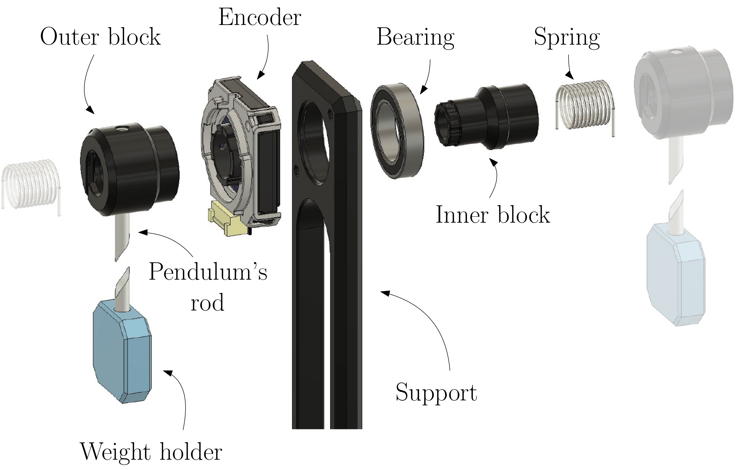
The pendulum segment is designed as a combination of off-the-shelf and 3D-printed components.
Requirements
- Spring
- Bearing
- Pendulum’s Support
- Pendulum’s rod
- Rotary encoder
- Pendulum’s block
- Inner block
- Outer block
- Weight holder
- Screws
- M3x14 hex socket button head screw (Qty.: at least 2x)
- M6x16 hex socket cap screw (Qty.: 1)
Instructions
-
The configuration of the pendulum segment is here: https://a360.co/3uP4RIG.
- Insert the bearing into the support
- Insert the inner block into the bearing
- Attach the encoder to support using 2 diagonally placed screws or all 4 screws (M3x14)
- Place the outer block onto the inner block and the encoder
- Insert pendulum’s rod with weight holder into the outer block
- Secure weight holder with a small screw if necessary.
- Insert the spring into the outer/inner block
- Attach the support to the frame with M6x16.

Encoder cable
Requirements
- 4-wire cable
- Length of the segment: from 40 cm to 1 m.
- Connector JST ZPDR-18V-S with 4 contacts SZPD-002T-P0.3
- Connector Molex 55935-0410 with 4 contacts Molex 56134-9001
- Crimping tool (recommended: PAD-11 ENGINEER)
Instructions
- Get desired length of the cable from the encoder to the FPGA Shield. Note, that the cable could be inserted into the support.
- On both sides, crimp the conductors and insert them into the connectors.
- For the JST ZPDR-18V-S, use the contact SZPD-002T-P0.3
- For the Molex 55935-0410 use the contact Molex 56134-9001
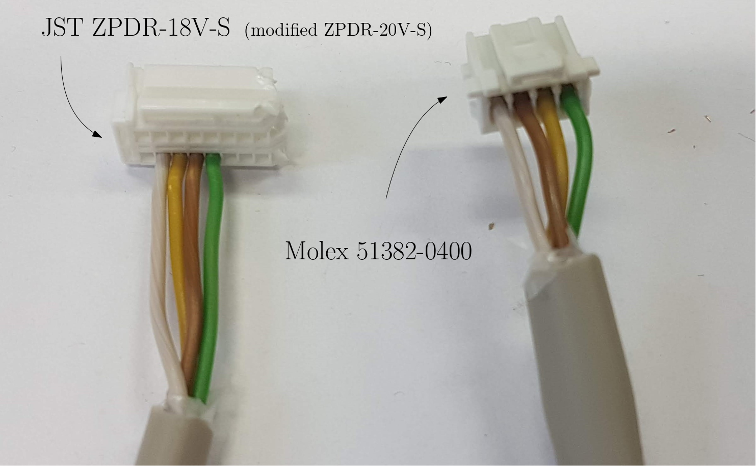
- See picture below of the desired cable configuration. Note, that because the JST ZPDR-18V-S was not available at the time of the assembly, we had to buy JST ZPDR-20V-S and cut off a part of the connector.
- Note, that the order of colors is not the same on both connectors.

Motor segment
Requirements
- NEMA17 1.8° stepper motor
- 3D-printed motor support: https://a360.co/3M9fMnV
- 3D-printed connecting block
- Motor Driver (Pololu Tic T249)
- Screws
- M3x14 hex socket button head screw (Qty.: at least 2x)
- M6x16 hex socket cap screw (Qty.: 1)
- USB-B cable for connecting motor driver to PC.
FPGA shield
Requirements
- DE0-Nano FPGA Board
- Custom-made PCB; see: https://github.com/ptrbroz/AA4CC_FK_model_sensors/tree/main/FK_fpga_shield
- Electrical components listed in the bill of materials.